 By Brenton Rowland Sept 2017.
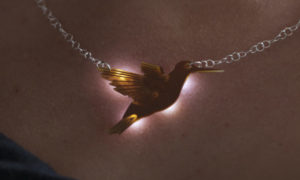
Our Science Club members all had a go at making one of these illuminated necklaces in August 2017.
The idea was not mine but copied from an Instructable by Other Machine Co. – “Light Up PCB Necklace”
Many processes and procedures had to be followed and the students gained insight into how an idea is taken from a CAD drawing to a finished piece of electronic jewellery.
- The Eagle PCB designs were modified to widen the PCB electrical tracks and use a larged button cell to power it.
- Eagle created the PCB shapes and exported Gerber files containing the PCB layout drawings
- FlatCam converted the drawings to GCode
- Autoleveller made micrometer adjustments to allow for uneven PCB surface
- Mach3 controlled a small CNC router to engrave, drill and cut out the necklace PCB shapes.
- PCBs were smoothed and cleaned ready to solder components
- The electronics were soldered onto the PCB. The LEDs are only 1.2mm x 0.8mm so some were challenging fine motor skills and magnifiers were required!
- Cleaned again, laquered, jump rings and chain were added to complete the necklaces
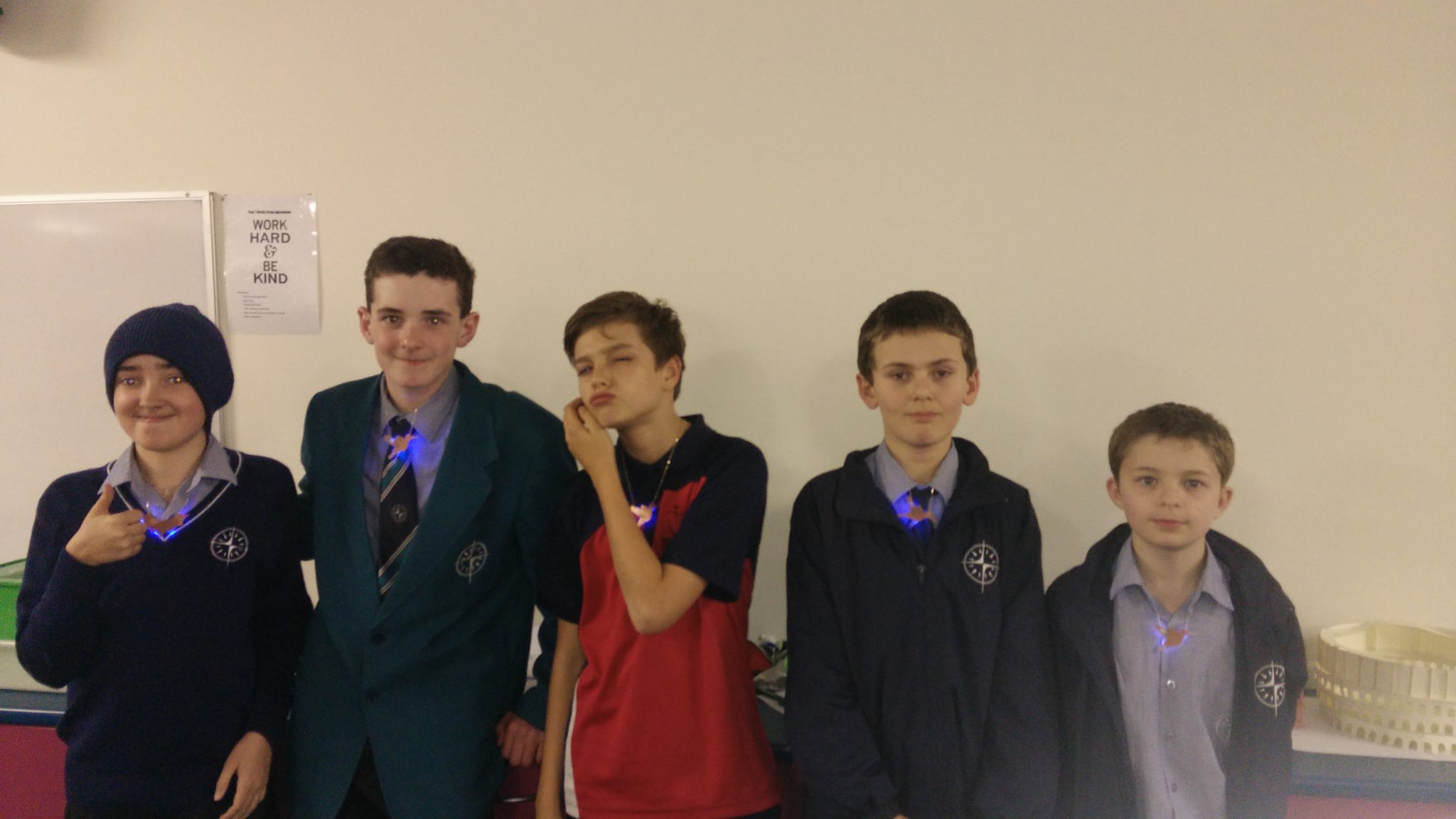
Here are the first 5 happy high tech jewellers…
Hummingbirds and Bats